« Proportional Flow Control Valves
About Solenoids
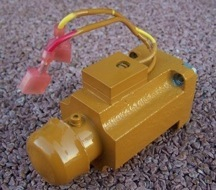
This picture shows the solenoid portion of the proportional flow control valve.
The purpose of the solenoid is to move the spools within the valve which spools then control the hydraulic fluid flow.
The solenoid positions the spools according to the DC current flowing through the solenoid coil and has a zero position that it’s plunger goes too when zero current is flowing in the solenoid coil.
The solenoid has two positions that the plunger will go to for a specific current amplitude flowing through the solenoid coil. One is not useable and one is useable for one is the pull position and one is the push position in the case of this proportional flow control valve where only the push position is used.
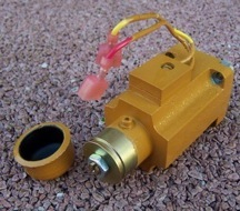
A screw is used to make a moveable mechanical stop which forces the solenoid to only use the push position of the solenoid plunger as the magnitude of current flow through the solenoid is changed. The calibration screw is protected by a rubber boot.
The mechanical screw stop must be set to the point where the solenoid plunger position is slightly less then the stop fluid flow position of the valve spools. This is the basic configuration of the types of solenoids that have been in use since the late 1980’s. The look and electrical connectors have changed over the years.
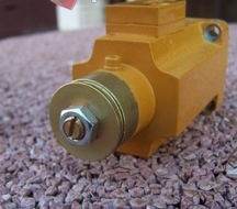
The calibration screw has a locking nut which nut must
be loosened to allow the calibration screw to be adjusted.
Calibration Steps
- Remove the electrical wires connecting to this solenoid.
- Loosen the locking nut.
- Turn the screw counterclockwise to stop tub rotation with grinder engine at full throttle.
- Turn the screw clockwise till the grinder tub slightly creep in rotation.
- Turn the screw 1/4 turn counterclockwise and lock the screw with the locking nut.