The RCB93 regulates engine loading by changing the magnitude of grinder material intake relative to the magnitude of the engine RPM change. The range of particle sizes in the ground material is a function of RPM and depend upon the RPM range. The range of particle sizes is lower in response to a controlled RPM range.
Description
The RCB93 control box is designed to automatically or manually adjust the CV98 or other proportional valves that meet appropriate specifications. The design of the controller makes it suitable for use in a variety of weather conditions. It has extensive weatherproofing features and is assembled with time-tested components to ensure long life in extreme as well as protected environments.
In MANUAL mode the TUB SPEED knob is used to linearly adjust the voltage output to the solenoid on the valve. The single turn potentiometer gives smooth, precise adjustments. The output is pulse width modulated (PWM).
In AUTO mode the output voltage is automatically adjusted based on input from a magnetic proximity sensor or a tachometer. The RANGE switch and ENGINE LOAD knob are used set the desired output voltage based on the incoming sensor signal. Thereafter, as the frequency from the sensor or tachometer increases the output voltage increases, and visa-versa. The output is pulse width modulated (PWM).
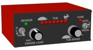
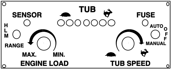
The FUSE light indicates the fuse is good.
The SENSOR light indicates an appropriate signal is being received from the sensor or tachometer
output.
The row of lights under the word TUB indicate the amount of voltage being output to the solenoid. The first light (under the turtle) indicates a low voltage output. As more voltage is sent to the solenoid the lights closer to the rabbit are lit.
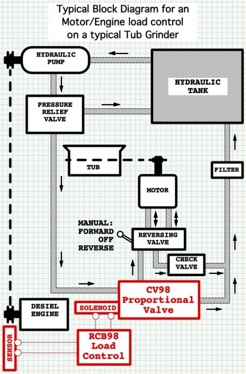
Typical Block Diagram for a Diesel Engine’s load control on a typical Tub Grinder
AUTO verses MANUAL
This control provides for AUTO (automatic) engine loading or MANUAL for setting a fixed TUB speed.
AUTO (automatic)
The AUTO-OFF-MANUAL switch is set to the AUTO position. The purpose of the AUTO switch position is to control and overcome engine overloading. Both knobs have a purpose when the AUTO-OFF-MANUAL switch is set to the AUTO position. ENGINE LOAD knob is used to set full load engine RPM. TUB SPEED knob is used to limit maximum TUB RPM.
MANUAL (TUB speed)
The AUTO-OFF-MANUAL switch is set to the MANUAL position. The purpose of the MANUAL switch position is to set a dialed rate of tub rotation. Only one knob has a purpose when the AUTO-OFF-MANUAL switch is set to the MANUAL position. TUB SPEED knob is used to set the TUB RPM.
Input Signal
In AUTO mode the output voltage is automatically adjusted based on input frequency from a magnetic proximity sensor.
The RANGE switch and ENGINE LOAD knob are used set the desired engine loading via the control’s output voltage which output voltage is directly related to the incoming frequency of the sensor’s frequency. Frequency is the speed at which sprocket teeth are passing the end of the sensor.
The SENSOR lamp is for troubleshooting the amplitude of the sensor signal. When the SENSOR lamp is ON solid and no flickering, the amplitude of the sensor signal is enough for that specific control box and does not indicate another control will work with that specific signal amplitude.
IMPORTANT: The input signal amplitude must be greater then one volt AC (rms). The typical amplitude is 3 to 5 volts rms when the sensor is spaced 1/16 inch from the tipi of the sprocket teeth.
- NOTE 1: Amplitudes of less then one volt rms may cause one control box to work while another will not.
- NOTE 2: Amplitudes of less then one volt rms may cause erratic control box functioning, jerking of the tub speed, and flickering of the SENSOR lamp.
Once the signal amplitude is greater then one volt rms, as the frequency from the sensor increases the output voltage increases(increases tub speed), and visa-versa. The output is a pulse width modulated (PWM) grounding on one end of the solenoid on the valve. The other end of the solenoid is connected to grinder’s 12 or 24 volts.
The FUSE light indicates the fuse is good when the fuse light is solidly ON and not OFF or flickering. Sometimes grinding dust can accumulate inside the fuseholder and cause connection problems even when a new fuse is inserted.
Setup
Setup AUTO loading of the engine:
- Start with the tub empty and the engine idle.
- Position the right hand TOGGLE SWITCH at AUTO for automatic engine loading.
- Position the RANGE toggle switch at M (Pointing down) to initially attempt to use the middle RPM range.
- Set the TUB SPEED knob fully clockwise pointing at the rabbit to eliminate the TUB SPEED knob from any limits upon tub RPM.
- Set the ENGINE LOAD knob fully clockwise.
- Set engine at the full throttle, ready to grind, RPM.
- Rotating the ENGINE LOAD knob from MIN to MAX should take the tub RPM from stopped to maximum. Or, position the RANGE toggle switch to H when the tub is not stopped when the ENGINE LOAD knob is at MIN. Or, position the RANGE toggle switch to L when the tub is not maximum when the ENGINE LOAD knob is at MAX.
- Rotate the ENGINE LOAD knob to a position where the tub just reaches maximum RPM.
- Start grinding by loading materials to be ground into the grinder.
- The ENGINE LOAD knob is ready to be used to decrease (knob clockwise) and increase (knob counterclockwise)
Knob Use
Normally, the ENGINE LOAD knob is the only adjustment necessary after the RANGE toggle switch is in the correct position. The ENGINE LOAD knob is only enabled when the right hand toggle switch is in the AUTO position.
Position the right hand toggle switch to AUTO for automatic loading of the engine according to the ENGINE LOAD knob setting. Both knobs serve different purposes in the control of engine loading when the right hand toggle switch is in the AUTO position.
Use of the ENGINE LOAD knob after setup. Position the right hand toggle switch to AUTO. Set the engine at full throttle. Load materials to start the grinding.
Rotate the ENGINE LOAD knob to decrease (knob clockwise) or to increase (knob counterclockwise) the loading of the engine. Similarly, rotate the ENGINE LOAD knob clockwise for a higher average engine RPM. Rotate the ENGINE LOAD knob counterclockwise for a lower average engine RPM.
The RANGE toggle switch serves the purpose of shifting the RPM range for the ENGINE LOAD knob which is the core of Knob Setup. Re-position the RANGE toggle switch to correct for the ENGINE LOAD knob running out of range during engine loading adjustments.
Troubleshooting
In case of complete control failure (i.e. TUB does not turn) emergency grinding procedure:
- Disconnect wires from valve solenoid.
- Bring grinder to normal grinding RPM
- Loosen locknut on end of solenoid
- Turn screw clockwise until a safe, slow TUB speed is obtained.
- Lock the locknut, and start grinding.
- Turn screw counterclockwise to reduce TUB speed if engine overloading is a problem.
Re-calibration after complete control failure return to using control box:
- Re-connect wires to valve solenoid.
- Install repaired or new control box.
- Put control box switch in OFF position.
- Bring grinder to normal grinding RPM.
- Loosen locknut on end of solenoid.
- Turn screw counterclockwise until the tub just starts to turn.
- Turn screw counterclockwise 1/4 turn to stop the tub.
- Lock the locknut.
- Turn control box to AUTO OR MANUAL and begin grinding.